
.jpeg?w=1800&h=1350)
Positioning small sheet metal parts accurately on a press brake requires three things: a repeatable bend-line reference, a reliable way to keep the blank square, and a safeguarding method that keeps hands away from the point of operation. A visible alignment line or magnetic squaring arm can support setup, but neither replaces the machine backgauge, approved tooling, a risk assessment, or a safety-rated guarding system.
The short answer: use a laser guide to make the intended bend line easier to see, use a squaring aid to control orientation, verify the setup on a sample part, and operate only within the press brake manufacturer’s safeguarding procedure.
Important: A positioning laser is a visual setup aid. It is not a safety light curtain or a laser AOPD, and it must never be treated as one.
Why are small parts difficult to position on a press brake?
Small blanks offer less surface area for stable contact with the backgauge or side reference. Their edges may also be close to the bend line, so a small positioning error can change flange length, angle consistency, or hole location after forming.
The safety risk also increases when an operator tries to hold a short part close to the tooling. The Fabricator’s safeguarding overview specifically notes that small parts can place fingers closer to the point of bending. The correct response is not to defeat a guard or reach farther into the die area; it is to redesign the setup, use appropriate workholding or support, and follow the employer’s risk assessment.
What does a positioning laser do?
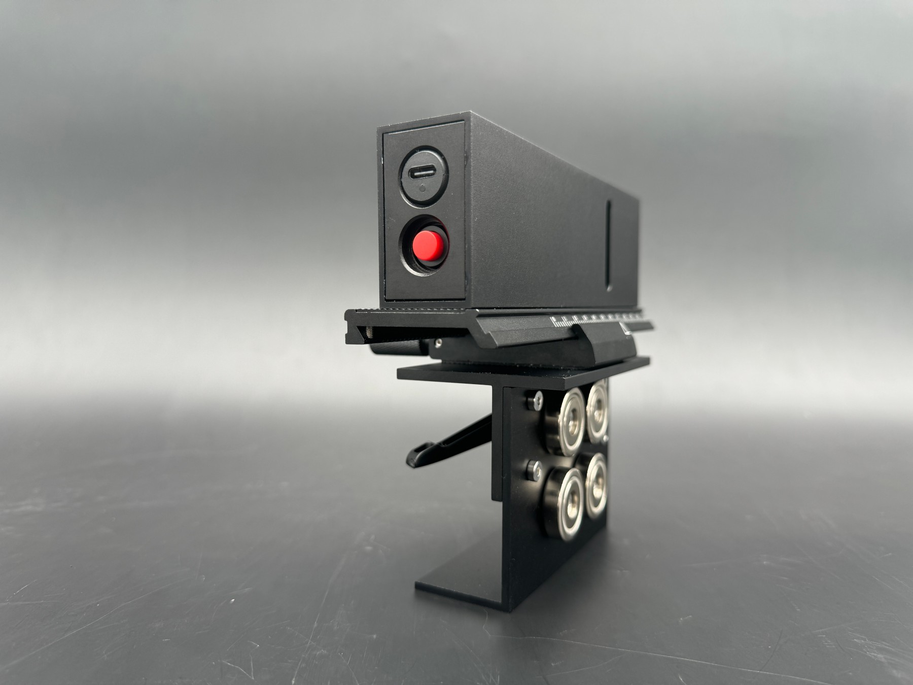
A press brake positioning laser projects a visible reference line onto the sheet. When installed and calibrated for the application, it can help the operator see where the planned bend line should sit relative to the tooling.
A laser guide is most useful for:
- Checking a marked bend line before a trial bend
- Supporting setup on blanks that are awkward to reference visually
- Providing a visible cue during changeover and first-piece verification
- Helping confirm orientation before the machine cycle begins
R-Laser’s press brake guide describes the same basic role: a visible line can support part positioning before bending and help reduce setup errors.
The Tranyond magnetic laser alignment device uses magnetic fixation and is listed for CNC press brakes. Because the product is an alignment aid, its position must be checked whenever tooling, machine setup, or bend geometry changes.
What does a magnetic squaring arm do?
A squaring arm gives the blank a repeatable side reference. This helps reduce rotation when the part is placed against the backgauge or another approved locating surface.
The Tranyond magnetic squaring arm is described for small parts and is listed at 270 × 175 × 40 mm with a weight of 1.8 kg. Those dimensions come from the current product listing and should be checked against the available bed space, tooling, clamps, and part path before use.
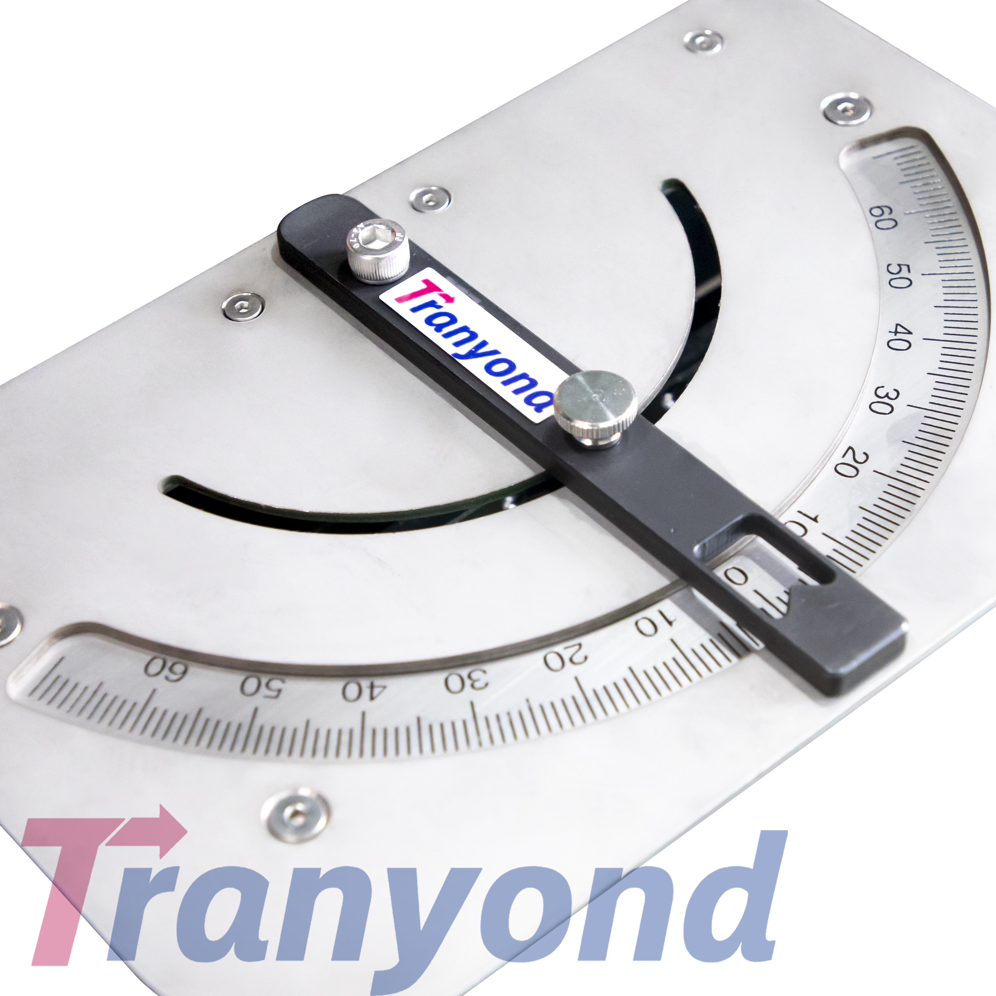
Related reading: a magnetic squaring arm is a physical side-datum fixture, not a laser guide or a safeguard. See how a press brake magnetic squaring arm works, including left vs right setup and when a fixture beats hand-holding.
Laser guide or squaring arm: which should you use?
| Setup need | Laser guide | Magnetic squaring arm | Use both? |
|---|---|---|---|
| See the intended bend line | Strong visual aid | Does not project a line | Useful when both line and orientation matter |
| Keep a short blank square | Limited by itself | Provides a physical side reference | Often helpful for first-piece setup |
| Check part orientation | Visual reference only | Physical alignment aid | Can provide two independent cues |
| Replace the backgauge | No | No | Neither replaces an approved backgauge setup |
| Provide machine safeguarding | No | No | Neither is a safety-rated guard or AOPD |
The best arrangement depends on the part geometry, available clearance, machine controls, and safeguarding system. Treat every accessory as part of the setup review—not as a universal solution.
How do you set up a small-part bend step by step?
1. Review the drawing and bending sequence
Confirm material, thickness, bend direction, flange size, inside radius, hole location, and the sequence of bends. Identify whether the part can remain supported without fingers entering the hazard area.
2. Inspect the machine, tooling, and safeguards
Follow the press brake manufacturer’s inspection and setup instructions. Confirm that tooling is seated and clamped, the backgauge is operating correctly, and all required safeguarding is active. OSHA’s powered press brake guidance should be considered together with applicable regulations, standards, and the employer’s risk assessment.
3. Install positioning aids with the machine in a safe state
Apply the facility’s lockout/tagout or approved setup procedure before placing or adjusting accessories near tooling or moving components. Ensure the magnetic base is seated on a clean, suitable surface and cannot interfere with the ram, clamps, tooling, backgauge, workpiece, or protective devices.
4. Calibrate the visible reference
Use a known reference, setup piece, or approved calibration method. Do not assume the projected line is correct simply because it is visible. Recheck it after moving the accessory or changing tooling.
5. Square and support the blank
Place the blank against the approved backgauge and side reference without forcing it. Make sure the squaring aid does not create a new pinch point or prevent the part from moving naturally during bending.
6. Run a controlled first-piece test
Use the machine’s approved setup mode and safe speed where required. Measure flange length, angle, and orientation after the first bend. Correct the setup through the machine controls, tooling position, or approved reference adjustment—not by placing hands closer to the dies.
7. Record the repeatable setup
Document the program, tooling, backgauge position, accessory position, material batch, inspection result, and any verified offset. A recorded setup is more reliable than relying on operator memory.
What must you verify before production?
Use this checklist before running the batch:
- The visible line matches the verified bend reference
- The side reference holds the part square without forcing it
- The accessory cannot collide with tooling, clamps, ram, backgauge, or the workpiece
- Safeguards remain active and effective throughout the cycle
- Hands and fingers can remain outside the point of operation
- The first piece meets flange, angle, and feature-location requirements
- The setup remains stable after several repeated cycles
If any item fails, stop and revise the setup.
What mistakes should you avoid?
- Confusing an alignment laser with a safety laser. A visible positioning line does not monitor the danger zone.
- Using the accessory instead of the backgauge. A visual or side reference supports setup; it does not automatically control flange depth.
- Skipping calibration. Magnetic mounting makes repositioning convenient, but every move requires verification.
- Ignoring the full motion envelope. Check the accessory against the ram, clamps, tooling, backgauge, and moving workpiece.
- Holding tiny parts too close to the dies. Use an approved alternative setup, support, fixture, or process when safe hand clearance cannot be maintained.
- Treating one successful bend as process capability. Verify repeatability across several pieces and material batches.
- Publishing undocumented offsets. Record the setup so another qualified operator can reproduce and inspect it.
Frequently asked questions
Can a magnetic laser alignment device replace the backgauge?
No. It provides a visible setup reference. Flange depth and repeatability still depend on the approved backgauge, tooling, machine controls, and verified process.
Is a positioning laser the same as a laser AOPD?
No. A positioning laser helps show a line. A safety-rated AOPD is part of a validated safeguarding system designed to detect intrusion near the hazard. Never use a positioning accessory as a safety device.
When is a magnetic squaring arm useful?
It can help when a small blank tends to rotate or when a repeatable side reference is needed. The part, tooling, and machine layout must provide adequate clearance.
Do magnetic accessories work on every press brake?
Compatibility depends on the mounting surface, machine geometry, controls, safeguarding, and motion envelope. The Tranyond laser product is listed for CNC press brakes, but the actual setup still requires a machine-specific compatibility check.
How often should the laser reference be checked?
Check it after installation, after any movement, after tooling or setup changes, and whenever inspection results suggest drift. Follow the accessory and machine manufacturer’s instructions.
Can these aids improve bend accuracy?
They can improve setup visibility and orientation consistency, but final accuracy also depends on tooling, backgauge repeatability, material variation, crowning, angle compensation, and operator procedure.
What should I do if the part is too small to hold safely?
Stop and use an approved alternative such as a fixture, support, different bend sequence, different tooling, or another forming method. Do not bypass safeguards or place fingers closer to the tooling.
Conclusion
For small press brake parts, accurate positioning is a system—not a single accessory. Use a visible reference to confirm the bend line, a suitable squaring aid to control orientation, and a verified backgauge and tooling setup to control dimensions. Most importantly, keep positioning aids separate from safeguarding: the machine’s approved guards, control system, safe operating procedure, and risk assessment remain essential.