
Bend allowance and bend deduction describe the same quantity — how much material a bend consumes — but they start from different measurements. Use bend deduction when your drawing dimensions run to the outside sharp corners; use bend allowance when your dimensions stop at the bend tangent points. When the K-factor and the angle convention are right, both methods return the same flat length.
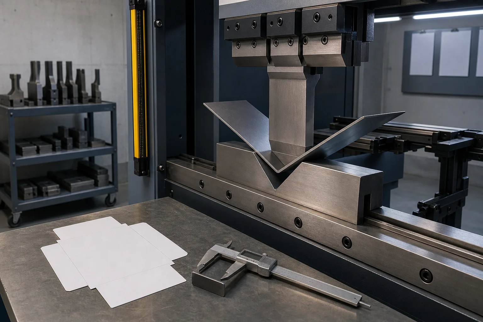
A flat blank does not become a bent part by folding; the material stretches on the outside of the bend, compresses on the inside, and one layer in between keeps its original length. That layer is the neutral axis. Bend allowance is the arc length of the neutral axis through the bend, and bend deduction is what you subtract from the outside flange dimensions to arrive at the same developed length. Choosing the wrong one — or feeding either of them an assumed K-factor — is the most common reason a blank comes off the laser either long or short.
What bend allowance and bend deduction actually measure
Three geometric references sit on every bend, and the naming only makes sense once you can point at them:
- Bend allowance (BA) — the developed length of the neutral axis through the curved region. It follows the material around the bend.
- Outside setback (OSSB) — the distance along either outside leg from its bend tangent point to the theoretical corner where the two extended outside faces intersect. That theoretical corner is the outside virtual sharp; it is not a physical point on the rounded bend.
- Bend deduction (BD) — twice the outside setback minus the bend allowance. It replaces the two setback distances with the real developed arc.
Bend deduction is therefore not "the material length inside the bend." It is the difference between adding up outside dimensions to the virtual sharp and adding up straight lengths plus the developed arc.
The four formulas you need
Define the inputs first, because most errors happen before any arithmetic starts:
- T — actual stock thickness, measured, not the nominal gauge.
- R — finished inside bend radius, as formed, not the punch tip radius.
- K — neutral-axis position ratio. If the neutral axis sits a distance d from the inside surface, K = d / T. It is dimensionless.
- θ (theta) — the angle bent from flat, in degrees: θ = 180° − finished inside included angle.
| Quantity | Formula |
|---|---|
| Neutral-axis radius | R + K × T |
| Bend allowance | BA = (π × θ / 180) × (R + K × T) |
| Outside setback | OSSB = (R + T) × tan(θ / 2) |
| Bend deduction | BD = 2 × OSSB − BA |
| Flat length from outside flange dimensions (F1, F2) | L = F1 + F2 − BD |
| Flat length from straight tangent lengths (S1, S2) | L = S1 + S2 + BA |
Three calculation rules keep the numbers trustworthy. Keep one unit system throughout — R and T in millimetres or both in inches, with K staying dimensionless. Evaluate the tangent in degrees; if your software wants radians, write the term as tan(πθ / 360) and still enter θ as degrees. And carry full precision through the intermediate values, rounding only the final flat length.
The angle convention deserves its own warning. A right-angle bend hides an angle error because the included angle and the angle bent from flat are both 90°. Everywhere else they diverge:
| Finished inside included angle | θ entered in the formulas |
|---|---|
| 90° | 90° |
| 120° | 60° |
| 60° | 120° |
| 135° | 45° |
Worked example: a 90° bend in 2 mm mild steel
Take a part with T = 2 mm, a finished inside radius R = 3 mm, an assumed K = 0.40, outside virtual-sharp flange lengths F1 = 40 mm and F2 = 30 mm, and a 90° included angle (so θ = 90°).
| Step | Calculation | Result |
|---|---|---|
| Neutral-axis radius | 3 + 0.40 × 2 | 3.8 mm |
| Bend allowance | (π × 90 / 180) × 3.8 | 5.969 mm |
| Outside setback | (3 + 2) × tan 45° | 5.000 mm |
| Bend deduction | 2 × 5.000 − 5.969 | 4.031 mm |
| Flat length (deduction route) | 40 + 30 − 4.031 | 65.97 mm |
| Flat length (allowance route) | (40 − 5.000) + (30 − 5.000) + 5.969 | 65.97 mm |
Both routes agree at 65.97 mm. If they disagree beyond rounding, do not average the answers — check the dimension endpoints, the angle convention, the units, and whether both calculations used the same R, T and K. Agreement proves the geometry and the arithmetic are consistent; it does not prove the assumed inputs match what your machine actually does.
Which method should you use? Bend deduction vs bend allowance
Bend allowance and bend deduction are not competing estimates — they are two entry routes into the same developed length. Pick the route by how your drawing is dimensioned, not by habit.
| Dimensions available on the drawing | Method | Operation |
|---|---|---|
| Outside flange lengths extending to the outside virtual sharp | Bend deduction | Add the flange lengths, then subtract BD |
| Straight lengths ending at the bend tangent points | Bend allowance | Add the straight lengths, then add BA |
| Inside flange lengths running to the inside virtual sharp | Neither, until converted | Subtract the inside setback, R × tan(θ / 2), to get the tangent length first |
"Inside dimension" names a surface, not an endpoint. A dimension may run from a square-cut end to the intersection of the extended inside faces rather than stopping at the tangent point. Convert it before feeding either formula, and check the extension lines on the drawing rather than trusting the label.
How to choose a K-factor you can defend
The K-factor is the weakest assumption in the whole calculation. It is not a material constant: the forming method, the tooling and the inside-radius-to-thickness ratio all move it. Common practice sits in the 0.33–0.50 band, and the neutral axis shifts inward from the 0.50T centreline as the inside radius tightens relative to thickness.
| Source position | Practical meaning |
|---|---|
| The Fabricator's bending basics series cites 0.446 as an average and commonly used K-factor for air bending (published 11 Jan 2018). | A defensible starting point for ordinary air bending in mild steel, not an answer. |
| ADH Machine Tool states plainly that a generic K-factor is an assumption, not a steel constant (published 2 Sep 2026). | Material, tooling and method must all be matched before the value means anything. |
| DIN 6935, cold bending of flat rolled steel, handles developed length, bend line, opening angle, minimum bending radius and minimum leg length using a correction factor k tabulated against the inside-radius-to-thickness ratio. | A tabulated, standard-based route instead of a single assumed K — and a reminder that the letter k does not always mean the same quantity across systems. |
The practical sequence that survives production: start from a defensible K, cut a trial blank, form one representative part from the same material batch on the same tooling and program, measure the actual inside radius, flange lengths and angle, then back-solve the K that reproduces your shop's real flat length. Record it per material and tooling combination. That recorded value, not the handbook value, is what your next job should use.
Five mistakes that ruin flat pattern length
- Entering the included angle as θ. A 120° included angle needs θ = 60°. On a 90° bend the error is invisible, which is exactly why it survives into production.
- Using nominal thickness. Rolling tolerance and coating change T, and T appears in both the setback and the neutral-axis radius. Measure the actual stock.
- Using the punch tip radius as the inside radius. In air bending the formed radius is not automatically the punch tip radius — it depends on the die opening and the material. Confirm the radius on a trial part.
- Treating a generic K-factor as a material property. Change the die opening, the material or the forming method and the value that reproduced your last flat length no longer applies.
- Extending the constant-radius model to hems, coined bends and arbitrary profiles. At a 180° fold the setback expression becomes undefined, and coining and hemming need process-specific development data rather than an unverified extension of the air-bending formula.
Keeping the blank and the machine honest
The calculation only pays off if the blank is located correctly and the result is measured. Three checks tighten the loop between the drawing and the finished part.
Put the bend line where the calculation says it is. A front position gauge holds the blank against a repeatable stop so the bend line lands on the die centreline instead of wherever the operator judges it. A 750 mm gauge with locating pins covers typical short-part work.
Measure the angle, do not assume it. Springback means the ram position that produced a good sample yesterday can be off today. A handheld angle measurer with 0.01° resolution over a 50°–180° range makes the difference between a measured correction and a guess.
Repeat the trial bend on the same tooling. A V16/V24 lower die lets you compare a narrow opening against a wider one on the same part, which is the quickest way to see how much the formed radius — and therefore the bend allowance — actually moves. Where surface finish matters, a mark-free lower die removes contact marking from the comparison so you are judging geometry, not scratches. For small trial batches and short-part development, a compact hydraulic table press brake rated for a 200 mm bend length carries the same calculation through to a real sample without occupying the production machine.
If you want the calculation reviewed against your drawing, send the part drawing, the actual material and the tool stack. Browse Tranyond press brake tooling or contact Tranyond with your drawing and machine details.
Frequently asked questions
Is bend allowance the same as bend deduction?
No. Both produce the same developed flat length, but they start from different measurements. Bend allowance is the arc length of the neutral axis through the bend and is added to straight tangent lengths. Bend deduction is twice the outside setback minus the bend allowance and is subtracted from outside flange dimensions measured to the virtual sharp.
How do I calculate bend allowance?
BA = (π × θ / 180) × (R + K × T), where θ is the angle bent from flat in degrees, R is the finished inside radius, T is the actual thickness and K is the neutral-axis position ratio. For a 2 mm sheet with a 3 mm inside radius, K = 0.40 and a 90° bend, BA = 5.969 mm.
What K-factor should I use for mild steel?
Start in the 0.33–0.50 band; The Fabricator cites 0.446 as a commonly used average for air bending. Then verify it with a trial bend on your own tooling and record the back-solved value per material and tooling combination.
Does the K-factor change when I change the die opening?
Yes. K depends on the material, the tooling and the inside-radius-to-thickness ratio, so it is not a material constant. Changing the die opening changes the formed radius, which changes the allowance and the required flat length — review the blank rather than adjusting the angle alone.
Why is my flat part consistently too long or too short?
Check four things in order: whether θ was entered as the angle bent from flat rather than the included angle; whether the measured thickness was used instead of nominal; whether the inside radius was measured on a trial part instead of copied from the punch tip; and whether the K-factor was recorded from this material and tooling. A consistent error is usually a systematic input error, not a formula error.
Can I use the same bend deduction for a hem or a coined bend?
No. The constant-radius model assumes straight adjoining legs and a finite outside virtual-sharp intersection; at a 180° fold the setback expression becomes undefined. Hems, coined bends and arbitrary formed profiles need process-specific development data.
Do bend allowance and bend deduction always agree?
They agree when the inputs and the dimension references agree. Convert each outside flange length to its tangent length with S = F − OSSB, and the equivalence L = S1 + S2 + BA = F1 + F2 − BD holds. If they disagree beyond rounding, check the endpoints and the units rather than averaging the results.
Does a CAD system make these formulas unnecessary?
No. CAD applies a bend table or a K-factor you supply. If the table does not match your tooling and material, the flat pattern it produces will be wrong with more decimal places, not less.
Sources and further reading
- ADH Machine Tool — The Bend Deduction Formula and the Geometry It Requires (2 September 2026)
- Industrial Monitor Direct — How to Calculate Bend Line Positions for CNC Press Brake (1 August 2026)
- JS Precision — Bend Allowance Formula: K-Factor & Springback (19 September 2026; cites ISO 2768-1:1989 and DIN 6935:2011)
- Modulus Metal — DIN 6935 Cold Bending of Flat Rolled Steel: Tolerance Tables (9 November 2025)
- The Fabricator — Press brake bending basics: Die angles, tonnage, and K-factors (11 January 2018)
Related press brake guides
- How to Choose Press Brake V-Die Opening and Check Tonnage
- How to Confirm Press Brake Tooling Compatibility Before You Order
- Mark-Free Bending: Roller Die or Protective Film?
Browse all Tranyond bending guides
A change in the formed inside radius changes the bend allowance and therefore the required flat pattern. Review the blank and finished dimensions whenever the die, the material or the forming method changes — and confirm the calculation with a trial bend on the material and tooling you will actually run.