
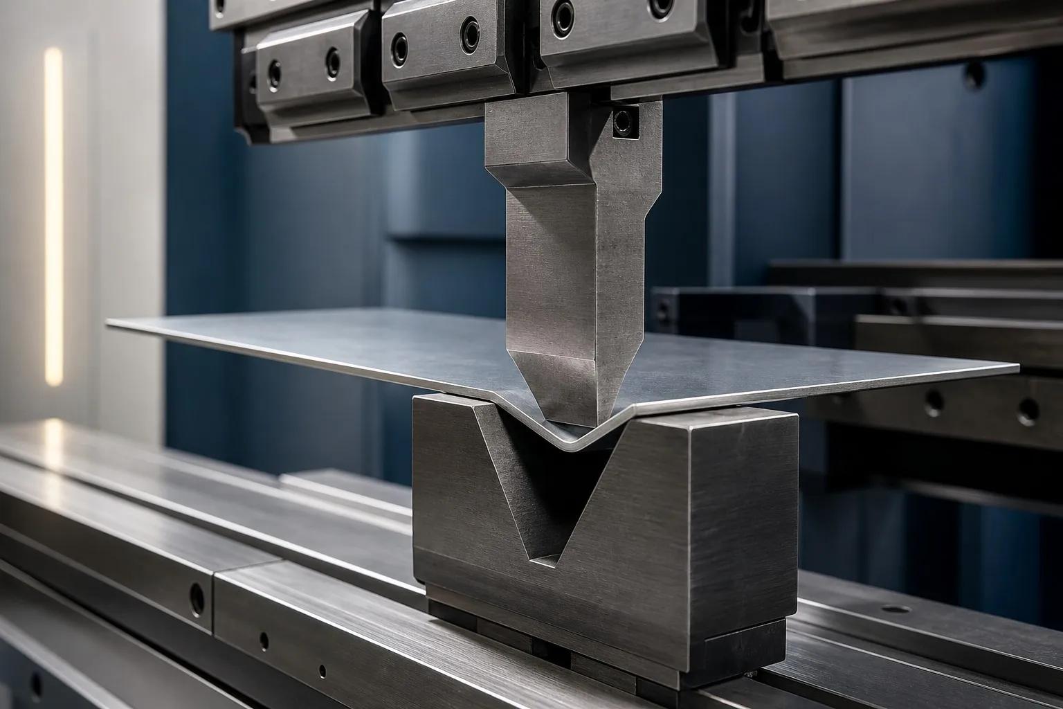
Select a press brake V-die opening by checking material, formed radius, minimum flange and required force together. A thickness-based ratio is a screening aid for air bending; it is not a complete setup specification. Verify the opening against the tooling manufacturer’s chart and the drawing.
What the V-opening changes
| Constraint | What to check | Why it matters |
|---|---|---|
| Material | Grade, strength range, thickness tolerance and rolling direction | Equal thickness does not mean equal bending behaviour |
| Inside radius | Drawing requirement and expected radius for the material and method | In air bending, the formed radius is not automatically the punch-tip radius |
| Minimum flange | Shortest supported leg, angle and die-shoulder geometry | A flange must remain supported throughout the bend |
| Force | Actual bend length and rated load of the complete tool stack | A narrower opening can increase load substantially |
| Surface finish | Permitted marks, contact condition and protective method | Geometry and shoulder condition affect contact marking |
Use thickness rules within their stated limits
WILA’s V-opening guide describes a 6–8-times-thickness rule of thumb for air bending ordinary steel up to about 3 mm thick. This is an initial selection range for that situation, not a universal rule for stainless steel, aluminium, high-strength steel or other forming methods.
Specify the actual material and bend angle when consulting a chart. Also confirm how the tool manufacturer measures the opening; catalogue conventions can differ. Avoid moving from a rule of thumb directly to a production program.
A practical selection sequence
- Read the drawing. Identify material, thickness, target angle, inside radius, bend length, shortest flange and nearby holes or cut-outs.
- Choose the forming method. Use air-bending data for air bending. Bottoming, coining, hemming and special forming require their own tooling and force assessment.
- Screen available openings. Compare the manufacturer’s suggested opening, natural radius and minimum flange with the part requirements.
- Check the complete load path. Verify machine, punch, die, clamp, holder and adapter ratings, including local loading and short-section restrictions.
- Review clearance and finish. Check punch travel, formed flanges, tooling ends, part removal and surface protection.
- Make and inspect a representative trial part. Record the material batch, tooling, program, resulting angle, radius, flange dimensions and marks.
Smaller or larger opening: evaluate the trade-off
A smaller opening may help meet a tighter radius or shorter-flange requirement, but only if the material, tool geometry and load limits permit it. Increasing the opening can reduce required force while changing the formed radius and supported flange. Neither choice is automatically better.
Changing the actual bend radius can also change bend allowance and the required flat pattern. Review the blank and finished dimensions when you change the die, rather than adjusting the angle alone.
Read tonnage ratings without mixing units
Keep the calculation and component ratings in one consistent unit system. Total force, force per metre and force per foot are different quantities. Kilonewtons, metric tonnes-force and US short tons-force also require explicit conversion.
- State the actual material and bend method used for the calculation.
- Use the loaded bend length, not simply the full installed die length.
- Check restrictions for concentrated, off-centre or short-segment loading.
- Use the lowest applicable limit in the machine-to-tool load path.
- Obtain a dedicated assessment for coining, hemming or special tools.
Frequently asked questions
Is V = 8t always correct?
No. It is a common screening rule for a limited air-bending application. The final opening must also meet material, radius, flange, finish and load requirements.
Will the inside radius equal the punch-tip radius?
Not automatically in air bending. The material and die opening influence the naturally formed radius. Confirm the radius for the actual tooling and forming method.
Can a larger V-opening remove all bending marks?
No. It may help reduce contact marking in a suitable setup, but damaged shoulders, contamination and surface requirements still need attention.
Can I use the same die and program for another material of equal thickness?
Recheck both. Material strength, ductility and springback can change the required force and the resulting geometry.
What should I do if a short flange is unsupported?
Stop and reassess the die geometry, part design or forming method. Do not rely on hand pressure to compensate for insufficient support.
Plan your tooling request
Send the part drawing and actual material information so the opening, punch and permitted load can be reviewed together. Browse Tranyond press brake tooling or contact Tranyond with your drawing and machine details.