
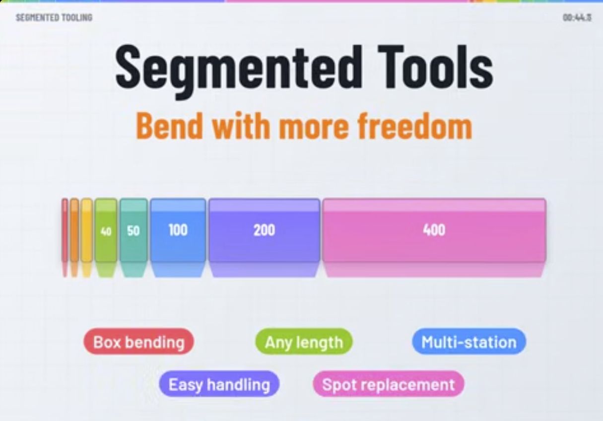
Segmented press brake tooling lets you assemble a working length from several shorter punch or die sections. This gives fabricators more flexibility when bending different part sizes, forming boxes, arranging multiple stations, and handling or replacing tools. The key is to combine compatible sections, keep their working surfaces aligned, and check the complete setup against the part and machine.
The TYD video below explains these benefits with a segmented tool kit and a simple box-bending animation. Here is how to apply the ideas when planning your next job.
Watch: Why Segment Press Brake Tools?
1. Build the tool length your part needs
The video illustrates an eight-piece kit with a combined length of 835 mm:
10 + 15 + 20 + 40 + 50 + 100 + 200 + 400 = 835 mm.
Each section contributes to the installed working length. For example, the illustrated 360 mm setup can be assembled from 200, 100, 50, and 10 mm sections. A different part may use another combination from the same kit.
These are the video's example dimensions. Available lengths and combinations depend on the tooling system and model; confirm the actual segment list before ordering. Choose the installed length from both the bend line and the space needed for already formed flanges. A longer tool can be useful on an open part, but extra length may obstruct a box or tray.
2. Create clearance for box and tray bending
Once a part has upright sides, the next bend becomes a clearance problem as well as a forming operation. An unnecessarily long punch can extend into those sides as the ram moves. Shorter sections let you arrange a tool length that fits the available space.
The video shows a four-sided box formed through four bends. As the flanges rise, the relationship between the tool ends and the formed walls becomes more important. Use the animation as a visual explanation of this relationship, then plan the real sequence from your drawing.
- Review the finished geometry. Identify the bend lines, flange heights, internal space, and access needed to load and remove the part.
- Plan the bend order. Check how each formed flange changes the clearance for the following operation.
- Assemble the required tool length. Confirm punch profile, die opening, and tool-end clearance together.
- Verify the setup and first part. Follow the machine's setup procedure and inspect dimensions, angles, and surface condition before continuing the batch.
Segmentation changes tool length. It does not change the punch throat, tool height, or machine daylight. Deep boxes and return flanges may still need a different punch profile or a revised sequence.
3. Arrange multiple forming stations
The video illustrates several tool sets on one bed: a small V-die station, a larger V-die station, and a hemming station. Separating these stations can reduce repeated tool changes when a part needs several operations.
A workable layout needs more than spare bed length. Check tool heights, clearance between stations, backgauge access, the machine's permitted loading arrangement, and the requirements of each operation. Hemming requires suitable tooling and its own force assessment. Confirm that the machine and tooling support the planned arrangement before using it in production.
4. Handle smaller pieces and replace worn sections
Shorter sections are easier to organize and move individually than a long tool with the same profile. The video compares a 100 mm piece with the full 835 mm length: it represents about 12% of that length. This is a length comparison; actual handling weight depends on the section's material and geometry.
Segmentation also makes local replacement possible. If one section becomes worn or damaged, you can assess that section for replacement instead of automatically replacing the full assembly. The replacement must match the required profile, working height, interface, and tolerances. Inspect the remaining sections and the assembled joint before returning the setup to use.
5. Keep the joints flush
The video's final setup lesson is essential: adjoining sections must form a consistent working line. A height step or misaligned section can affect the bend and leave a visible transition on the part.
- Start with a matched set intended to work together.
- Clean the seating surfaces and inspect the section ends for damage.
- Seat, align, and clamp the tools according to the holder and tool instructions.
- Check the assembled working line and inspect a trial bend across the joints.
The video advises using pieces from the same set and avoiding mixed batches or brands. Treat any proposed mixed assembly as a compatibility check, even when its nominal dimensions appear similar. See our press brake tooling compatibility guide for the information to confirm.
Questions to answer before choosing a segmented set
Does segmented tooling increase bending capacity?
Segmentation provides flexibility in length and layout. Determine the allowable bending force from the machine, holders, punches, dies, material, and installed setup. Do not treat the machine's total tonnage as the allowable load for a short tool section.
Can every box be made with a short punch?
No. Tool length is one part of the clearance check. Punch shape, flange height, bend sequence, and part removal space also determine whether the operation is possible.
What should I send when asking for tooling advice?
Provide the machine and clamping details, a tool drawing or clear interface photos, the part drawing, material and thickness, bend lengths, required angles and radii, and the planned sequence. Include your existing segment lengths if you want to extend a set.
Choose the set around the job
Use segmented tooling where adjustable working length, flange clearance, multiple stations, or individual section handling will help your workflow. Match those benefits to the part geometry and the complete machine setup.
Browse the Tranyond press brake tooling catalog or contact Tranyond with your drawing and machine details to discuss the required interface and segment configuration.
Video source: TYD, Why Segment Press Brake Tools. Further reading: WILA's tool length guide, which explains how bend length and bending freedom influence tool selection. Segment dimensions vary by system.