
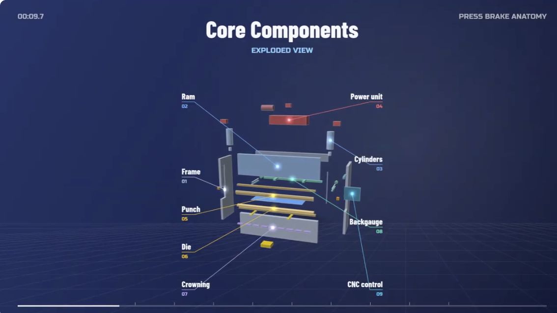
A CNC hydraulic press brake bends sheet metal by driving an upper punch toward a lower die. Its frame carries the load, the ram and cylinders move the punch, the hydraulic power unit supplies force, the backgauge locates the workpiece, and the CNC coordinates the bend. Crowning compensates for machine deflection, while guarding and sheet supports address protection and handling.
The Press Brake Anatomy animation below shows how the systems work together. The animation represents a CNC hydraulic machine; available axes, drives, guards and tooling vary by model.
Watch: Press Brake Anatomy
The 55-second video shows an exploded component view, eight system explanations and a complete bending cycle. Source: Press Brake Anatomy EN 16x9 — Sheet metal pro.
Main press brake parts at a glance
| Component | Main function |
|---|---|
| Frame and bed | Carry bending loads and provide the machine's structural reference. |
| Ram / upper beam | Move the punch through the bending stroke. |
| Hydraulic cylinders | Convert hydraulic pressure into ram movement and forming force. |
| Hydraulic power unit | Supply and control pressurized oil through a motor, pump, tank and valve block. |
| Punch, die and clamps | Contact and form the sheet; locate and secure the tooling. |
| Crowning system | Compensate for ram and bed deflection along the bend length. |
| Backgauge | Provide a positioning reference for the workpiece and flange dimension. |
| CNC control | Program the bend sequence and coordinate the fitted machine axes. |
| Safety devices | Protect the operating zone as part of the machine's safeguarding system. |
| Front supports / sheet followers | Support the sheet during loading and, where equipped, follow its movement. |
How the eight systems work
1. Frame: the load-bearing structure
The video depicts side frames, a bed and a tie beam forming a welded structure, with stress relief after welding. It also highlights the C-shaped throat. Throat depth affects clearance around the side frames; it is one part of the overall space available for a part, alongside daylight, stroke, tooling height and formed-flange clearance. Confirm these dimensions on the actual machine drawing.
2. Ram and cylinders: controlled movement
The ram carries the upper tooling. Two cylinders move it vertically in the animation, while position feedback helps synchronize its two ends, labelled Y1 and Y2. This illustrates a synchronized hydraulic arrangement, rather than a feature of every press brake. Ram-position control helps keep the tool line parallel; it does not eliminate material variation or the need to measure the finished bend.
3. Hydraulics: power and motion control
The animated power path runs from motor to pump, valve block and cylinders. The motor drives the pump, and the hydraulic circuit controls pressure and oil flow to produce force and movement. The video highlights proportional valves for force and speed control. Hydraulic power, CNC commands and position feedback work together; the animation's displayed values are examples, not a machine capacity or accuracy claim.
4. Punch and die: where the sheet forms
The upper punch presses the sheet into the lower die opening. In the video's air-bending example, a deeper stroke produces a more closed angle. Final results also depend on the material and springback. The V-opening affects the inside radius, required force and minimum flange length.
The animation shows V = 8t and a broad 6–12t range, where t is sheet thickness. Treat this as an illustration, not a universal selection rule. WILA's air-bending guidance gives 6–8t as a general steel starting point; material, radius and tooling load limits still need checking. Use our V-die opening and tonnage guide for the selection process.
5. Crowning: compensation along the tool line
A loaded ram and bed can deflect, creating different angles at the centre and ends of a long bend. The animation exaggerates this deflection and shows wedges lifting the central region to compensate. Bystronic explains crowning as compensation for machine deflection and describes mechanical and hydraulic approaches. The correct setting depends on the machine and job; crowning is distinct from synchronizing the ram's two ends.
6. Backgauge: the positioning reference
The illustrated backgauge uses servo drives, ball screws and linear guides to position its fingers. The sheet is located against those fingers before forming. Their position helps establish the flange dimension. The drawing, bend allowance, actual tooling and gauging surface must agree; a programmed backgauge number is not automatically the finished flange length on every part.
7. CNC: coordinating the job
The control screen shows a graphical four-bend program and coordinates Y1, Y2, X, R, Z1, Z2 and V. It also displays a collision-check result. Those are features illustrated by this animation. Confirm the actual controller, software options and machine geometry before relying on simulation. A successful screen simulation still requires an approved setup and inspection of the first part.
8. Safety and support: protection and handling
The video includes a laser guard beneath the punch, front supports and a foot pedal. A real guard's protective function depends on the device, its integration, operating mode and correct setup. Supports assist sheet handling; the foot pedal commands a cycle. These functions are different.
OSHA's powered press brake guidance identifies point-of-operation hazards, trapping between a rising workpiece and the ram face, and accidental cycling from foot controls. Follow the machine manufacturer's safeguarding and operating procedures. A positioning aid, backgauge or pedal does not by itself establish a safe operating setup.
CNC axes: Y1, Y2, X, R, Z and V
The following names describe the arrangement illustrated in the video. Axis naming, available travel and which movements are powered vary by manufacturer and model.
| Axis | Typical meaning in this arrangement | Practical role |
|---|---|---|
| Y1 / Y2 | Vertical positions of the two ram ends | Control the stroke and synchronize the upper beam. |
| X | Backgauge movement toward or away from the tooling | Set the workpiece's gauging position. |
| R | Backgauge height | Align the fingers with the required gauging surface. |
| Z1 / Z2 | Lateral positions of the individual backgauge fingers | Place reference points along the bend line. |
| V | Crowning adjustment in the illustrated machine | Compensate for deflection along the tool line. |
V-axis crowning and V-die opening are different terms. The V-axis adjusts a compensation system; the die's V-opening is a tooling dimension. Changing one does not replace selection of the other.
What happens during one bending cycle?
- Position: the backgauge establishes the programmed reference and the workpiece is located and supported.
- Approach: the ram moves toward the sheet under the machine's control and safeguarding sequence.
- Form: the punch loads the sheet over the die; ram synchronization, hydraulic control and crowning act together.
- Dwell and return: the illustrated cycle includes a dwell, then the ram returns so the part can be removed or repositioned.
The animation compresses these movements into a visual explanation. It does not provide operating speeds, pressure settings or a setup procedure for a particular machine.
Checks before choosing a machine or tooling
- Start with the part: material grade, thickness, bend length, target radius, flange sizes and finished geometry.
- Check the machine envelope: rated force, usable bending length, throat depth, daylight, stroke and backgauge travel.
- Confirm the tooling interface: punch and die profile, working height, clamping system, load rating and clearance through the full sequence.
- Confirm installed features: actual axes, crowning system, controller functions, guarding and sheet-handling equipment.
- Validate a representative part: assess the required load and inspect angles, dimensions, clearance and surface condition before production.
For a tooling enquiry, contact Tranyond with the machine model, clamping photographs or drawings, current tooling dimensions and a representative part drawing. This information is more useful than an axis count alone.
Frequently asked questions
What is the difference between a press brake ram and bed?
The ram is the moving upper beam carrying the punch in the arrangement shown. The bed supports the lower tooling. Both form part of the load path, and their deflection can affect angle consistency along a bend.
What do Y1 and Y2 mean on a CNC hydraulic press brake?
Y1 and Y2 identify the controlled vertical positions at the two ram ends in a synchronized hydraulic arrangement. Feedback allows the control to coordinate those ends. They are not backgauge axes or bending-angle measurements.
What is the purpose of a press brake backgauge?
The backgauge gives the workpiece a repeatable positioning reference. Depending on the fitted axes, its fingers can move in depth, height and lateral position. The finished flange still depends on the part geometry, tooling and bending calculation.
Is crowning the same as Y1/Y2 synchronization?
No. Y1/Y2 synchronization coordinates the ram ends. Crowning compensates for deflection along the bend length. They address different sources of variation and can work together.
Does every press brake have all the axes and features shown?
No. The video illustrates one CNC hydraulic configuration. Other machines use different drives, axis layouts, crowning systems, controls and safeguards. Check the actual specification and representative parts before choosing equipment.
Related guides and sources
- What Is Press Brake Tooling? Punches, Dies and Key Components — focus on the forming tools.
- How to Confirm Press Brake Tooling Compatibility Before You Order — check the machine-to-tool interface.
- Why Use Segmented Press Brake Tooling? — plan tool length and box clearance.
- Press Brake Automation: Features and Investment Checks — evaluate additional equipment and controls.
Source basis: the Sheet metal pro animation provides the component sequence and illustrated configuration. WILA, Bystronic and OSHA references linked above provide tooling, crowning and safeguarding context.